This is an old revision of the document!
Composite materials
Carbon-Fibre-Reinforced Polymers (CFRP) are now widely used in aerospace industry thanks to their high strength-to-weight ratio. However, the numerical simulation of CFRP laminates up to failure is not trivial: laminates have anisotropic mechanical properties and laminate damage results from a combination of microscopic mechanisms (fibre brittle failure, fibre-matrix debonding, matrix ductile failure and delamination) that are not easily described at a macroscopic level.
My objective was to implement a material model for composite plies with woven fibre reinforcement in Metafor. This model is inspired by the meso-model proposed by P. Ladevèze and O. Allix [1-2] for unidirectional composites as well as the 2D model for woven composites proposed by C. Hochard [3].
The idea is to describe the laminate as a stack of 3D orthotropic plies separated by 2D interfaces. In a direction parallel to the fibres, the plies are elastic and subject to brittle fracture; in shear, an elastoplastic behaviour is assumed and progressive damage is introduced. The 2D interfaces between the plies are elastic with progressive damage. Practical information on the orthotropic materials and damage evolution laws is available on the Metafor web page.
One interesting feature of Ladevèze and Allix's work is that most parameters of the constitutive laws can be linked to physical quantities. Therefore, these parameters can be identified with suitable experimental tests.
 Figure 1. Cyclic loading of a laminate sample with ply orientation $[(+45^\circ/-45^\circ)_n]_S$ : comparison between experimental results and Metafor results.
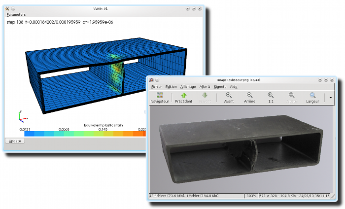 Figure 2. Finite element simulation (Metafor) of an impacted stiffener made of woven carbon fibre laminate
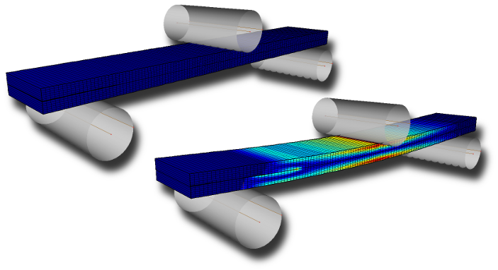 Figure 3. Finite element simulation (Metafor) of an End-Notched Flexure (ENF) test. It consists in a 3-point bending of a sample with an artificial mid-plane delamination. ENF tests are used to determine the mode II interlaminar fracture toughness of laminates.
 Figure 4. Impact simulation : (left) experimental setup for impact testing at UCL-IMAP lab. (Prof. Pardoen), (right) finite element model of the impact test; the impactor is represented as a rigid sphere having the same mass and kinetic energy as the experimental impactor.
 Figure 5. Impact simulation with finite elements (Metafor) on a quarter of a plate : maximum of the orthotropic damage variables $d_{11}$, $d_{22}$ and $d_{12}$, ranging from 0 (blue) to 1 (red).
References
[1] P. Ladevèze, E. Le Dantec. Damage modelling of the elementary ply for laminated composites. Composites Science and Technology, Vol. 43, pp. 257-267, 1992
[2] O. Allix, P. Ladevèze. Interlaminar interface modeling for the prediction of laminate delamination. Composite Structures, Vol. 22, pp. 235-242, 1992
[3] C. Hochard, P.-A. Aubourg, J.-P. Charles. Modelling of the mechanical behaviour of woven-fabric CFRP laminates up to failure. Composites Science and Technology, Vol. 61, pp. 221–230, 2001
Back to main page