This is an old revision of the document!
Shearography
Introduction
I am really no expert in shearography, so I will quote J.-F. Vandenrijt [1] for a proper definition: Shearography records the interference pattern between a speckle object wavefront and itself laterally displaced through an optical shearing device. Such interference patterns, so-called shearograms, are recorded at different instants between which the inspected object undergoes a certain stress (thermal, mechanical, pressure variation, vibration). The numerical difference between two shearograms gives rise to an interferogram which allows observing the derivative of the full-field displacement of the object under stress. A presence of defect induces a local signature in the interferogram.
In short, this technique is able to produce a fringe pattern which represents the derivative of the vertical displacement of the surface of the object. Defects in a structure can produce local perturbations of this pattern under appropriate loading, which is why shearography is used in non-destructive testing (NDT).
Marc Georges, from the Centre Spatial de Liège, proposed a master thesis project in collaboration with the Nonlinear Computational Mechanics group. The objective was to combine experimental tests at CSL with finite element simulations, to determine whether simulations can accurately predict the experimental fringe pattern generated by typical defects.
We were lucky enough to have two motivated students to work on this topic: Georges Crabus [2] focused on the experimental aspects in the CSL laboratory and Arthur Lismonde [3] made finite element simulations of the experiment. Arthur used ANSYS, which was available at the university where he went on Erasmus. However, we wanted to make a test requiring a particular post-processing of the results, so I made simulations on my own with my personal code.
Problem description
Several composite plates (10cm*15cm) were made of epoxy resin reinforced with carbon fabric. In practice, one or several holes were drilled in the back of the plates to simulate defects. In the numerical models, two kinds of defects were considered: either one circular hole or a circular piece of Teflon inserted between two plies. In the experimental setup, the plate is fixed to a static frame and its surface is heated up with a light. In view of the time constants of the mechanical and thermal phenomena, one can integrate the heat equation in time and solve a static mechanical problem (small deformations) at each time step. The only difficulties are the orthotropic thermal and mechanical properties of the material and the post-processing step turning the finite element results into a shearogram.
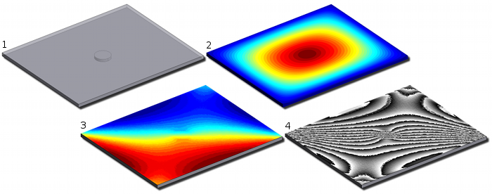 Figure 1. Results obtained with my personal code, visualized with Gmsh: (1) geometry of the plate with a circular hole, (2) vertical displacement of the upper face, (3) derivative of the vertical displacement, (4) shearogram.
One can see in Fig. 1 the finite element results obtained when the plate is heated up with a flash, which is represented by a constant heat flux applied for a few microseconds. The influence of the hole is visible on the shearogram. However, it is well-known that defects are harder to detect with this technique when they are located deeper in the structure. One possibility is to use a time-varying heat source instead of a flash and to apply a Fourier transform to the sequence of shearograms that are recorded over a period of time.
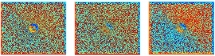 Figure 2. Phase offset of the Fourier transform of shearograms obtained with my personal code. The defect is a Teflon insert and the excitation is a sinusoidal heat flux: (left) shallow insert (1mm), excitation 1Hz; (center) deep insert (3mm), excitation 1Hz; (right) deep insert (3mm), excitation 0.1Hz.
References
[1] J.-F. Vandenrijt, N. Lièvre, M. Georges. Improvement of defect detection in shearography by using Principal Component Analysis. Proceedings of Conference on Interferometry XVII: Techniques and Analysis, 2014
[2] G. Crabus. Contrôle non-destructif par shearographie : développements expérimentaux de méthodes de stimulation thermique. Master thesis, Université de Liège, 2014
[3] A. Lismonde. Contrôle non-destructif par shearographie : simulations thermomécaniques de composites à renforts tissés. Master thesis, Université de Liège, 2014