This is an old revision of the document!
Micro Electro-Mechanical Systems
Background
I worked on a research project over microelectromechanical systems (MEMS) in the Aerodynamics group of Prof. Essers. This project was a collaboration between several research groups of the Université de Liège: Aerodynamics, Mechanical Vibrations (Prof. Golinval) and Applied and Computational Electromagnetics (W. Legros). My objective in this project was to simulate the deformation of microactuators taking into account the damping effect of air. These microactuators had to be manufactured by IMTEK and tested in the vibrations lab.
Problem description
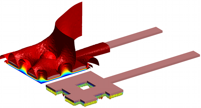
I designed the geometry of the actuators together with Véronique Rochus and Guillaume Sérandour from the Mechanichal Vibrations group. The shape and dimensions of the actuators were strongly limited by manufacturing constraints. Therefore, we started with a microplate as suggested by IMTEK specialists. An example of such plates is shown in Fig. 1; although this is not represented in the drawing, the extremities of the beams are clamped so as to maintain the structure a few microns above the base of the chip. The square holes are imposed by the manufacturing process. The vibration of the plate is induced by the electric potential difference between the plate and the square electrode which is fixed to the chip.
 Figure 1. Geometry of the micro-actuator (length=300$\mu m$, width=100$\mu m$, thickness=2$\mu m$). The aluminium plate is 2$\mu m$ above the electrode.
Numerical simulations
My first task was to design an automated way to calculate the mesh deformation of the air domain when the actuator moves. The difficulty was to keep an acceptable aspect ratio of the deformed mesh elements, which was of course critical between the plate and electrode. It also had to couple the different programs needed to make the coupled simulations:
- a fluid dynamic finite volume parallel software written in C by Didier Vigneron;
- a mechanical finite element software, OOfelie, written in C++ by Open Engineering;
- a C++ code of my own, which calculated the electrostatic force and the mesh deformation.
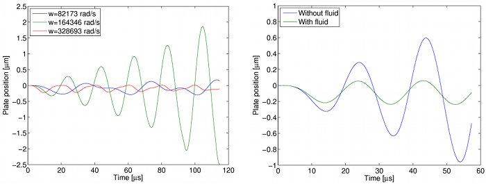
An external script called the different codes in turn and converted the input/output files to ensure data compatibility. Fig. 2 shows results of the electric simulation on a quarter of the plate. Electromechanical simulations were performed at different excitation frequencies (Fig. 3, left) and a full electromechanical-fluid simulation was made at the resonance frequency (Fig. 3, right).
 Figure 2. Electric scalar potential and electric force acting on the plate, calculated with my own code and visualized with Gmsh.
 Figure 3. Vertical displacement of the plate : (left), electromechanical simulation (OOfelie+my code) for an excitation frequency equal to $0.5\,\nu_r$, $\nu_r$ and $2\,\nu_r$, where $\nu_r$ is the resonance frequency; (right), electromechanical simulation with/without fluid coupling (OOfelie+my code+Didier Vigneron's code) at the resonance frequency.
Back to main page
