Table of Contents
3D Meshers (Volumes)
Transfinite Mesher
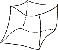
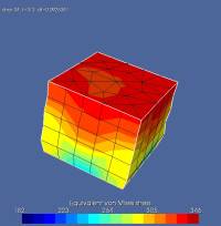
Metafor possesses a simple transfinite mesher, which is able to mesh hexahedra (object with 6 sides, such as a cube). For more complex geometries, it is necessary to divide it into hexaedra or use external meshers (Samcef, TetGen, …) and import the mesh in Metafor (see Reading SAMCEF files).
Preliminary note: To mesh a Volume, all its Sides and Curves must be meshed first !
With auto-detection
Auto-detection is possible if the Skin has 12 edges, each of which possesses only one line.
TransfiniteMesher3D(volumeset(number)).execute(type)
number | number of the Volume to mesh |
type | = True if mesh elements must be generated (CELL_HEXA)= False if only nodes must be generated (useful to debug only) |
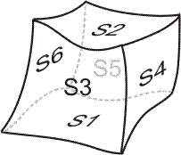
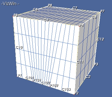
In this case, the Skin must be defined with the orientation shown below:
which means that
skin = add(Skin(1));
for i in [1,2,3,4,5,6]:
   skin.push(sideset(i))
where the number used in the push function are the number of the Sides included in the Skin.
Without auto-detection
This case is the most general, and can be applied to any Skin with the shape of a hexaedron. The definition of the skin must no longer be as the above figure shows, which means the sides can be “pushed” in the skin in any order.
The mesher needs a set of 12 sets of Curves, where each of these sets defines an edge of the hexaedron.
mat = ((mat11, ..., mat1nbmax), ..., (mat121, ..., mat12nbmax))
TransfiniteMesher3D(volumeset(number)).execute2(mat, type)
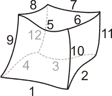
where number is the number of the hexahedral Volumeto mesh, and mat is a Python tuple with 12 components. Each component is a tuple which contains the number of the curves which constitute each edge. Each of these 12 edges can be made of a different number of curves.
These 12 tuples must be ordered as shown below:
Example:
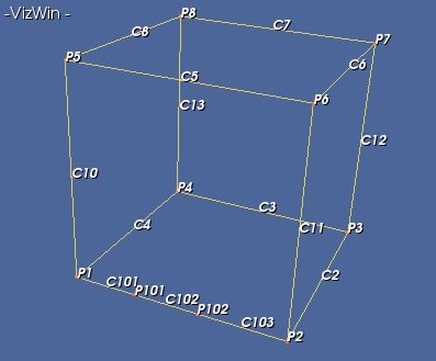
The hexahedral domain above can be meshed with the command:
TransfiniteMesher3D(volumeset(1)).execute2( ((103,101,102),2,3,4,5,6,7,8,10,11,12,13) )
or
TransfiniteMesher3D(volumeset(1)).execute2( (5,11,(103,101,102),10,7,12,3,13,8,6,2,4) )
or
TransfiniteMesher3D(volumeset(1)).execute2( (6,12,2,11,8,13,4,10,5,7,3,(101,102,103)) )
or
...
leading to:
Transfinite 3D mesher with non-uniform mesh elements distribution
This is done with the commands:
MesherTFI3D =TransfiniteMesher3D(volumeset(number))
MesherTFI3D.setEnableDistribution()
MesherTFI3D.execute(type, tri) ou MesherTFI3D.execute2(mat, type)
when one if the edges is already discretized using a mesh elements distribution.
Note : By default, the parameter setEnableDistribution is set to True.
Mesher by extrusion
This method can be used, but could be improved upon: density non-constant along the extrusion direction, improvement of meshing speed, giving the extruded nodes as groups (internal ones, external surface, …). For now on, a Side, a Skin or a Group can be extruded along any direction, with any number of elements.
The geometry associated to the extrusion can also be created (only for a Side). For a Skin or a Group, we can create the Points and Curves associated by extrusion to the Points and Curves of the object.
Example
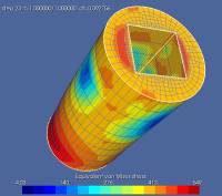
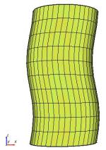
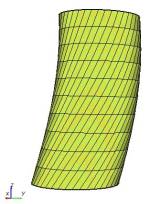
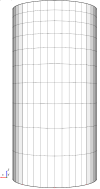
Extrusion of a circle pierced by a square (see apps.qs.extruMesher3d and apps.qs.extruMesher3dTx or apps.qs.extruMesher3dTorsion apps.qs.extruMesher3dDist03 for modified extrusions).
The definition and meshing of the circle can be seen in the the file. To extrude the result (Side #1):
mesher = ExtrusionMesher3D(sideset(1), groupset(1))
mesher.setFillGroup(True)
mesher.setDirection(0.0,0.0,1.0)
mesher.setLength(length)
mesher.setNbOfLayers(nLayers, dist = 1.0)
mesher.setAnglefct(fctAngle)
mesher.setXfct(fctX)
mesher.setYfct(fctY)
mesher.execute()
grpNo = mesher.getLastLayer(no)
| Group 1 | all the mesh element refer to this group (the FieldApplicator is applied to this group) |
| setFillGroup() | fills Group 1 with the nodes of the mesh |
| setDirection | direction of the extrusion (by default = z) |
| setLength | length of the extrusion |
| setNbOfLayers | nLayers : number of extruded elements |
| dist : ratio between the length of the last and first element (default : dist = 1.0) | |
| setAnglefct(fctAngle) | Application of a rotation of slices around extrusion vector (direction 'z' but starting from origin!!!) |
| fctAngle | One parameter defining rotation of slices function in degrees (t) - t=[0,1] ATTENTION : fctAngle(0) = 0 |
| setXfct(fctX) | Application of a modification of the generatrice direction in X Direction |
| setYfct(fctY) | Application of a modification of the generatrice direction in Y Direction |
| fctX/fctY | One parameter defining modification of generatrice : fct(t) - ATTENTION t=[0,Length] and fctX/fctY(0) = 0 |
| execute | execute the extrusion |
| getLastLayer(no) | returns the group grpNo (number no) which contains the nodes of the last layer |


Example 2
In a same way, a planar face meshed with triangles can be extruded in 3D to be meshed with prisms (see apps.monosMeca.monoTrac3dPenta).
Creation of the geometry
General case: Extrusion of a''Side'', a ''Skin'' or a ''Group''
After the extrusion of a Side, a Skin or a Group, the geometry can also be extruded from a Side with the function:
mesher.createGeometryOn(Side, NoGObject, geometry)
Geometrical objects are created and numbered starting from NoGObject.
The function createLineAbove can create only one Line corresponding to the extrusion of a Point :
line = createLineAbove(pt1, NumLine, NumPtOnTop, geometry)
Particular case : extrusion of a Side
To create a geometry after the extrusion of a Side, this function is used:
mesher.createGeometry(NoGObject, geometry)

Side 
Geometrical objects are created and numbered starting from NoGObject.
Récupération des objets géométrique
The retrieval of the created geometrical objetcs is done with the functions:
Vol1  = mesher.getVolumeOnTop(side1)
side  = mesher.getSideOnTop(curveOrSide)
curve = mesher.getCurveOnTop(pointOrCurve)
point = mesher.getPointOnTop(ptref)
| Vol1 | |
| side | Side created from the object curveOrSide (which corresponds to a Curve or a Side of the extruded object). If : curveOrSide = Curve → the returned Side is tangent to the extrusion direction. If: curveOrSide = Side → the extrusion direction is a vector which is normal to the returned Side |
| curve | Curve created from pointOrCurve (which corresponds to a Point or a Curve of the extruded object) If : pointOrCurve = Point → the returned Curve is tangent to the extrusion direction. If: pointOrCurve = Curve → the extrusion direction is a vector which is normal to the returned Curve |
| point | Point created from ptref (Point of the extruded object) |
The geometry is created in the test cases apps.welding.welding and aspCrushing.tests.threeD.smoothStripRoughTool.
<important note>
CAREFUL, after creating the geometry, the Volume, returned by the function mesher.getVolumeOnTop(side) must be added with the push command to the FieldApplicator in place of the group (groupset(1) of the constructor of the object ExtrusionMesher3D). In the case where only one layer of elements is found in the extrusion direction, the group (groupset(1) of the constructor of the object ExtrusionMesher3D) must be added with the push command in the FieldApplicator, whichever the extruded entity (Side, Skin or Group).
</note>
Mesher by extrusion of revolution
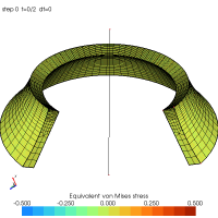
Axisymmetric extrusion of a meshed side. The extrusion can be open ($0 < \mbox{angle} < 360^\circ$) or close ($\mbox{angle} = 360^\circ$).
To this day, no reconstruction of the extruded geometry exists. Groups should be used to set boundary conditions.
mesher = RevolutionExtrusionMesher3D(gobject, group, axe, angle=180.0)
setAngle(angle)
mesher.setNbOfLayers(10)
mesher.execute()
| gobject | Meshed 2D geometrical entity |
| group | Group father of the 3D mesh elements |
| axe | Line which defines the revolution axis |
| setAngle | Angle of the extrusion (in degrees 0.0 < angle ⇐ 360.0 - default = 180.0) |
| setNbOfLayers | number of extruded elements |
| setFillGroup | fill the reference group with all nodes (base & generated) |
| execute | executes the extrusion |
| getLastLayer | return the group of the last layer (if not closed extrusion) |
